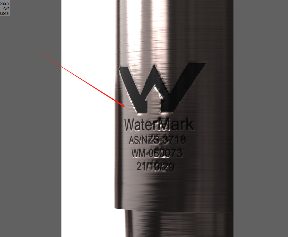
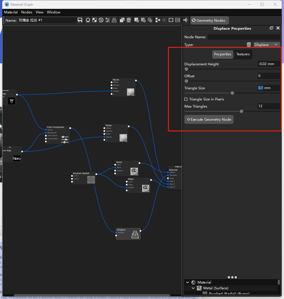
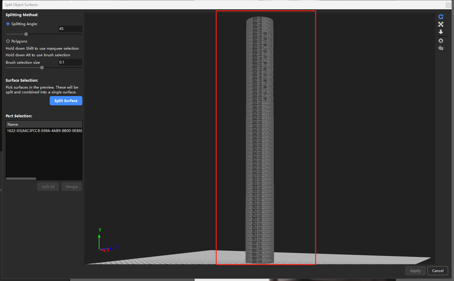
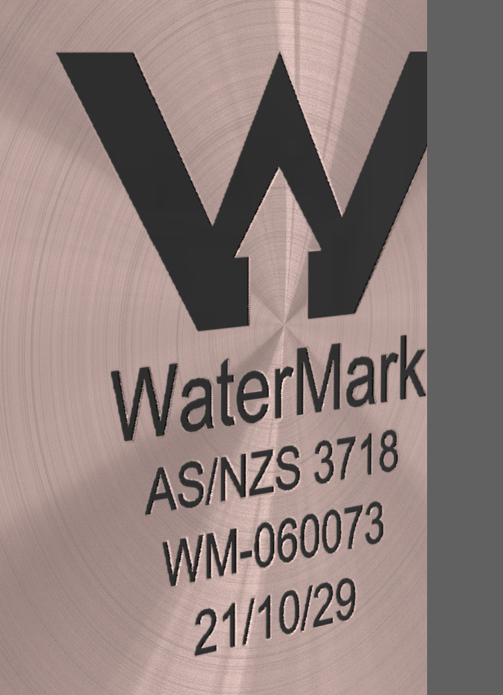
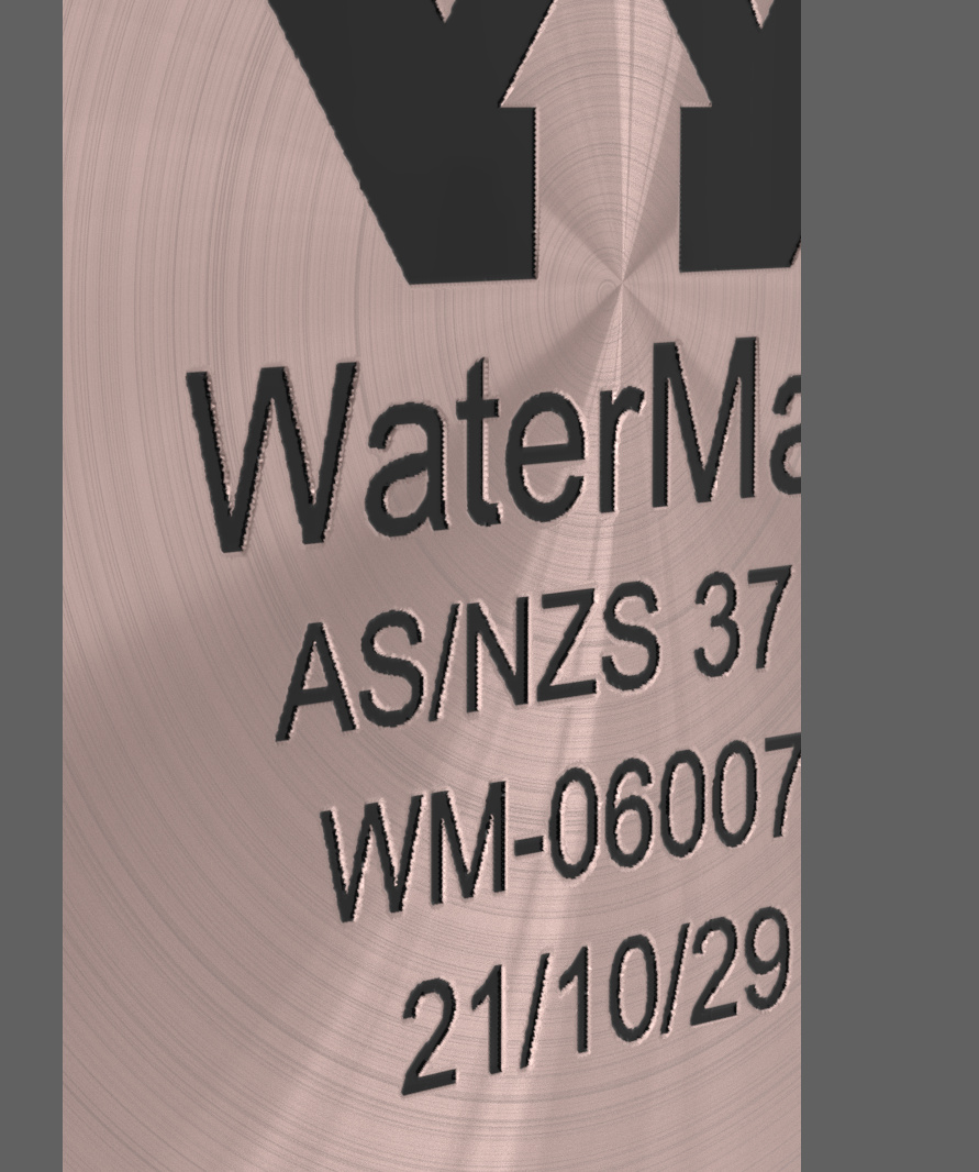
Anyone met the situation like the following before, I added the displacement as I did before, but it turned out to be like the Image 01, and I don’t know why. Image 02 and Image03 are the material graph and the surface. Does anyone have any idea about this?
Greetings, for me it looks like the displacment maps have left any damage on the surface, that’s why I always create my own real displacment maps and the associated normal maps, if I look at the edges, I would think that the resolution is in that area not high enough. In my experience Keyshot works better with real normal\display maps, if I have problems with the maps, I create my maps in ZBrush and Photoshop or in the free program ShaderMap 4. I hope it helps.
I wouldn’t personally use displacement for such things but a normal map. I’m not convinced displacement maps are the right thing since they are basically a bitmap (pixels) turned into actual geometry based on a triangle size.
So while your bitmap might have a really high resolution you will still have the 0.1 mm of edge length to deal with. You can lower that setting but it will create so much geometry while it’s not really a key feature of the object.
Much easier to get it done using a normal/height map. If that doesn’t give a satisfying result it’s better to just model the logo debossed in the CAD software itself. That will create a clean model with way less geometry compared to use a displacement with a very low triangle size.
Oskar brings up an argument that I hadn’t thought of before, because I only ever use real geometry and the norm/displ. maps only as a support to avoid oversized files and with so many triangles in the finished file as are absolutely necessary.
Your mesh appears fairly dense which is good. As Christian mentioned your resolution is not high enough. In other words, triangle size appears too high at .1, try decreasing it to .005 and increasing the max triangle count should also help. I agree with Christian and Oscar though, a normal map would be a better solution. If you are concerned about performance with high triangle counts you can disable the displacement while working or import NURBS and use the re-tesselate feature. Once you’re ready to render enable the displacement or re-tesselate to increase the triangle count.
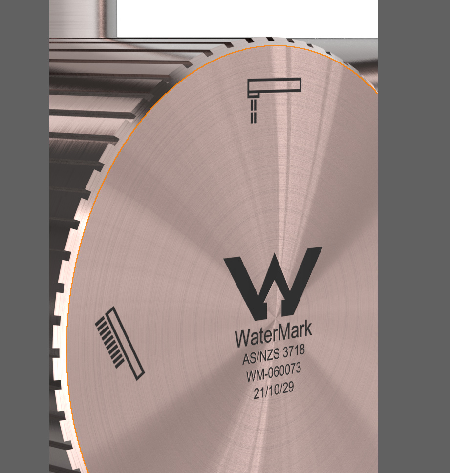
I found the reason why it turned out to be like that is not about the resolution of the texture map but the model. because I got good displacement with the same texture on the other surface.
Yes, normal map will give more precise information to simulate what happened in the real world, and I tried what you said about lower the setting but it turned out to be the same result, and I get a good result with the same texture map and displacement setting on the other model, so I think the reason maybe is for the model not texture map or displacement setting.
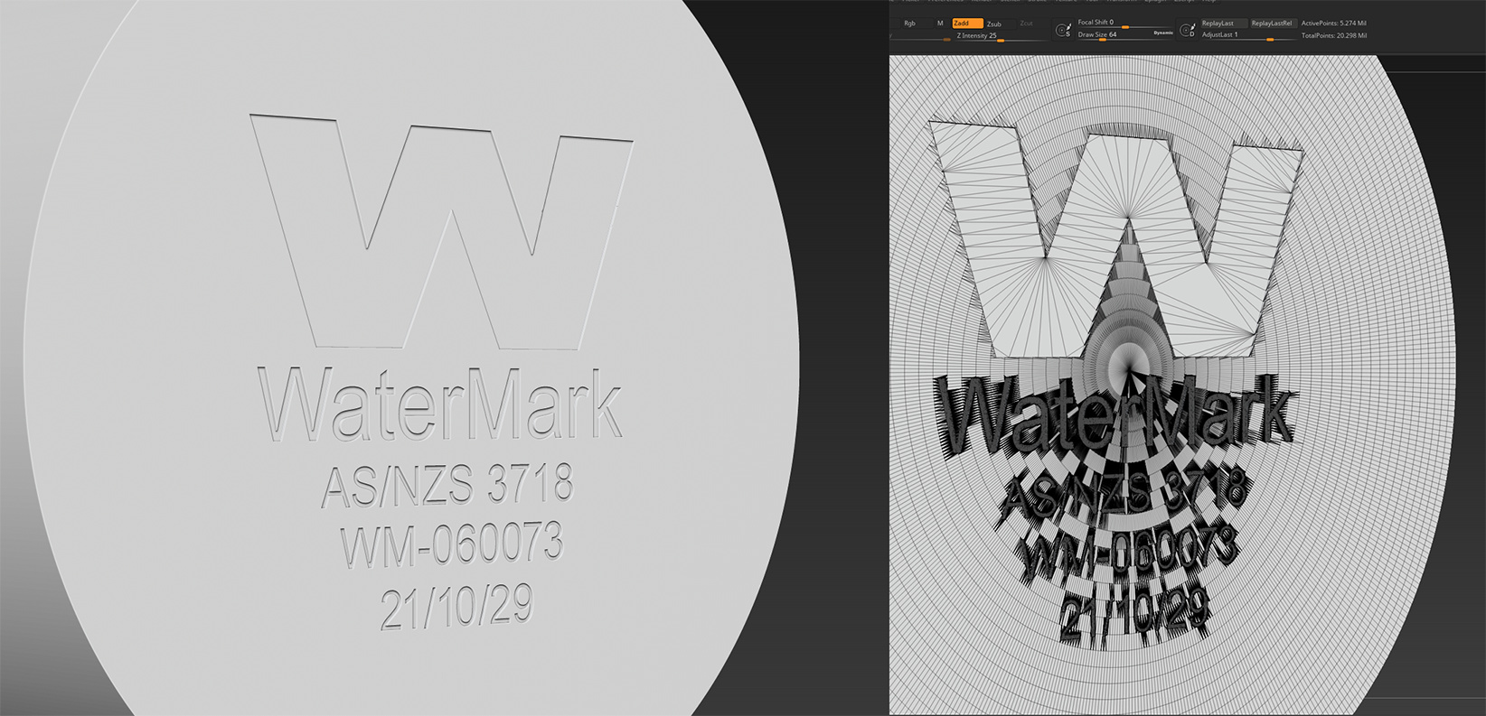
The big difference is that it’s much easier to displace something on a flat surface I think. If you look at the wireframe you’ll notice already a lot of edges which are small on the cylinder shape. If you use a displacement on those that will create even more edges which should give depth but also not collide with each other or overlap so you will get artifacts.
You have to realise I think that a displacement map will actually change the geometry of your model while a normal/bump map basically is a kind of ‘cheat’ which only affects the light while nothing changes to the geometry.
I think you can actually export the displacement as well so to get an idea of what the displacement does, try to export your model as obj/fbx and than look in a 3D program how the wireframe looks. That makes it easier to understand why displacement is not always the right solution besides it’s most of the time a more accurate way it’s not easy for software to get it done nicely on curved surfaces.
If you would deboss the text in a CAD program and export it as a obj/fbx you would notice it uses way less points to get the same done. That might result in some letters being not as round as you like but most of the time enough to get a right picture if you don’t look up close. But if you use cad it uses a vector based text and not a pixel based image which is already easier and saves a translation step.
I actually don’t think there are many programs which could do this very nicely on this tiny scale with surface modelling. Sometimes a trick with software is to enlarge the object so you give the program more space to calculate it and afterwards resize it again.
I would love to know if there is software really good at these kind of things with displacement maps but from my experience they always have certain limitations and taking a look at the wireframe helps to realise why.
My solution would be, I create a real geometry and if necessary a map for the type color and than the export to Keyshot (creation time approx. 45 minutes)